-
-
Notifications
You must be signed in to change notification settings - Fork 237
External ADC
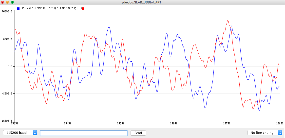
Here is a list of the most frequent analog to digital converters that can be used as I2S source by the framework. When you have a new device I recommend to start with the streams-i2s-serial sketch so that you can verify the data that you receive. A typical 2 channel int16_t audio signal might look as this:
Some modules only provide data on one channel and sometimes the other channel contains noise! So there is no point in trying any other sketch before you have a clear understanding of your module!
The framework uses the following default I2S pins for the ESP32:
- PIN_I2S_BCK = 14
- PIN_I2S_WS = 15
- PIN_I2S_DATA_IN = 32
Please double check the actual settings in AudioConfig.h for your Processor. You can also change the pins in your sketch:
  auto config = i2sStream.defaultConfig(RX_MODE);
  config.pin_bck = 14;
  config.pin_ws = 15;
  config.pin_data = 22;
  i2sStream.begin(config);
Some processors (the ESP32) support input and output at the same time. For this case you can use
  auto config = i2sStream.defaultConfig(RXTX_MODE);
  config.pin_bck = 14;
  config.pin_ws = 15;
  config.pin_data = 22; // output
  config.pin_data_in = 23; // input
  i2sStream.begin(config);
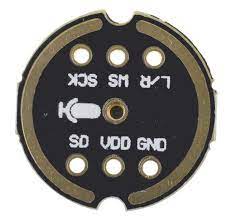
INMP441 Mems Microphone
The INMP441 is a high-performance, low power, digital-output, omnidirectional MEMS microphone with a bottom port. The complete INMP441 solution consists of a MEMS sensor, signal conditioning, an analog-to-digital converter, anti-aliasing filters, power management, and an industry-standard 24-bit I²S interface. The I²S interface allows the INMP441 to connect directly to digital processors, such as DSPs and microcontrollers, without the need for an audio codec in the system.
| INMP441 | ESP32 |
|---|---|
| VDD | 3.3 |
| GND | GND |
| SD | IN (GPIO32) |
| L/R | GND |
| WS | WS (GPIO15) |
| SCK | BCK (GPIO14) |
- SCK: Serial data clock for I²S interface
- WS: Select serial data words for the I²S interface
- L/R: Left / right channel selection When set to low, the microphone emits signals on one channel of the I²S frame. When the high level is set, the microphone will send signals on the other channel.
- SD: Serial data output of the I²S interface
- VCC: input power 1.8V to 3.3V
- GND: Power groundHigh
I2SStream i2sStream;
auto cfg = i2sStream.defaultConfig(RX_MODE);
cfg.i2s_format = I2S_STD_FORMAT; // optional because default setting
cfg.bits_per_sample = 32;
cfg.channels = 2; // optional because default setting
cfg.sample_rate = 44100;
cfg.is_master = true; // optional because default setting
i2sStream.begin(cfg);
The sample_rate is just a proposal and you can adjust it to your needs. Please note that the data is provided only on one channel as int32_t and that cfg.bits_per_sample = 16 might most likely just produce noise on one channel that you might have to filter out e.g. with a ConverterFillLeftAndRight!
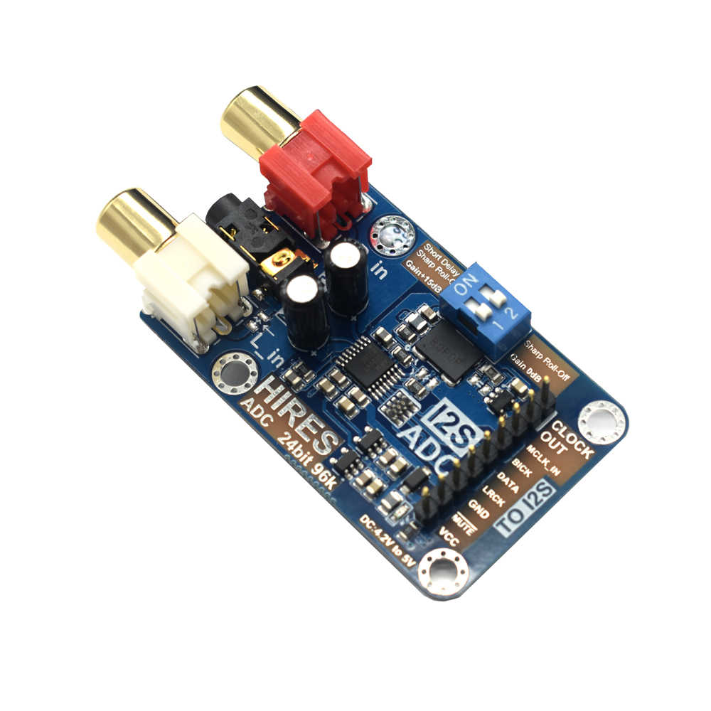
Usually you do not need any master clock, but unfortunately we need to feed this module with a master clock signal from the ESP32, if the ESP32 is acting as master.
| i2s-ADC | ESP32 |
|---|---|
| MCCLK_IN | RX_0 (GPIO3) |
| BICK | BCK (GPIO14) |
| DATA | IN (GPIO32) |
| RLCLK | WS (GPIO15) |
| GND | GND |
| MUTE | - |
| VCC | VIN 5V |
I2SStream i2sStream;
auto cfg = i2sStream.defaultConfig(RX_MODE);
cfg.i2s_format = I2S_STD_FORMAT; // or try with I2S_LSB_FORMAT
cfg.bits_per_sample = 32;
cfg.channels = 2; // optional because default setting
cfg.sample_rate = 44100;
cfg.is_master = true; // optional because default setting
// this module needs a master clock if the ESP32 is master
cfg.use_apll = false;
cfg.pin_mck = 3;
i2sStream.begin(cfg);
The sample_rate is just a proposal and you can adjust it to your needs. Please note that the data is provided on both channels as int32_t!


