Prerequisites
Important Note: Make sure to use a stable power supply, recommend not using the USBs of a computer beyond flashing, especially MacBooks as they don’t supply enough current and results in unexpected behavior of the ESP32 and/or PN532.
Make sure you have the following installed and/or setup:
-
A development board with an ESP32 chip, any board should be fine as long as it has an ESP32 or ESP32-C3 chip, ESP32-S2 and ESP32-S3 are also supported but has to be compiled for it.
-
A PN532 NFC Module
- This needs to use the SPI protocol
- Avoid using wires longer than 15cm or you’ll run into stability issues
- For the red board from Elechouse, there should be a DIP Switch on it and a small table to the side that indicates the switches states for each protocol, for SPI this should be 0 and 1 which means left ⬅️ switch down ⬇️ and right ➡️ switch up ⬆️
- Please be aware that some clones of this modules have cheap components that are going to cause issues of instability and signal range
- This needs to use the SPI protocol
Important Note: Both the ESP32 and the PN532 have to be using the same power supply otherwise they won’t be able to communicate.
The project follows the Arduino default wiring for the SPI protocol which is the following:
| ESP32 Pin | <-> | PN532 Pin |
|---|---|---|
| VCC* | <-> | VCC* |
| GND | <-> | GND |
| GPIO18 | <-> | SCK |
| GPIO19 | <-> | MISO |
| GPIO23 | <-> | MOSI |
| GPIO5 | <-> | SS |
*3.3V from the 3V3 pin should also work, however, only 5V from the VCC pin has been extensively tested.
For the MH-ET D1 Mini, the related SPI pins would be located here

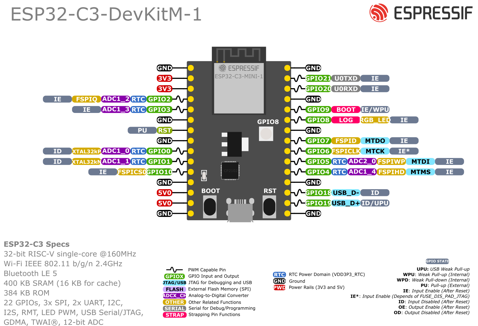
For an ESP32-C3 Dev Board, the SPI Pins are SS: 7, SCK: 4, MISO: 5, MOSI: 6