RTGI Plugin: DDGI based on Voxelization, Global SDF and multiple fantastic tricks.
This method mainly based on DDGI. We use Cascade-Global-SDF and Voxelization to replace hardware ray tracing. We also did a lot to reduce overhead.
- Infinite Scroll
- Cascaded probes
- Relocate probe origin when view direction changed (For better view frustum coverage).
- Progressive Frame Update
- SRGB Blend
- Classify
- Temporal Filter
- Probe Relocation
- Clipmap and AABB Scroll are used to reduce Voxelization overhead
- Easy to tune parameters
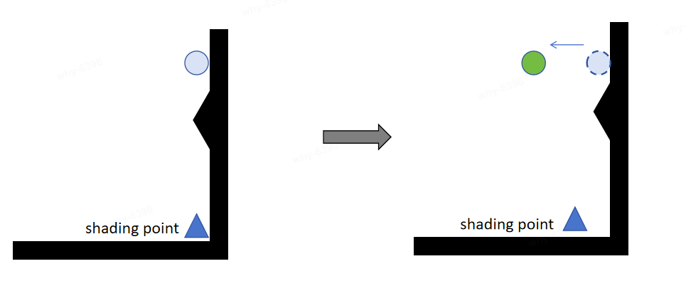
It's cost a lost time to recompute all the probe data when the camera moved. As shown in the figure below, we can just update those probes which in blue area obviously.
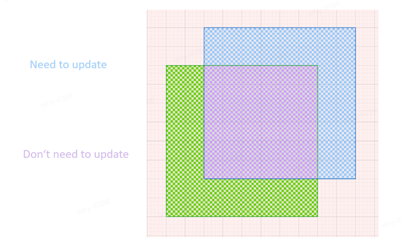
-
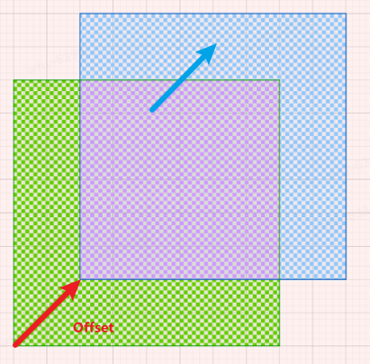
The center of the original probe volume is referred to as the Scroll Anchor, and the probe volume will also update its position as the camera moves:
-
When there is an overlapping region (purple area), in order to reuse the overlapping area, after the Probe Volume moves, record the ProbesScrollOffsets. When sampling a probe in the new probe volume, we will add the ProbesScrollOffsets to the probe coordinates:
(probeCoords + ProbesCounts + ProbesScrollOffsets[cascadeIndex].xyz) % ProbesCounts
-
-
When the probe volume moves away from the probe volume at the Scroll Anchor and they are no longer overlapping, we will reset the position of the Scroll Anchor.
- We use 4 cascade probe volumes. The four cascade probe volumes have same probe counts.The only difference between them is the probe spacing (The distance of two adjacent probes).
- With 4 cascade probe volumes, we can apply probes to cover lager scene with lower overhead.
- Our the largest cascade distance scale is 10.0f.
const float cascadesDistanceScales[] = { 1.0f, 2.0f, 5.0f, 10.0f }; - Probe Spacing in first cascade is
200*200*200by default. - Probe Count in one cascade is
20*20*10by default. - So the largest probe volume will cover
400m * 400m * 200m. - You can tune
Probe Spacing,Probe Count,cascadesDistanceScales[]by your demands.
- Our the largest cascade distance scale is 10.0f.
- 层级之间光追会有轻微跃变(通过混合相邻层级减轻)
This part is significant to speed up DDGI. You can read
Classify.usfto get more information.
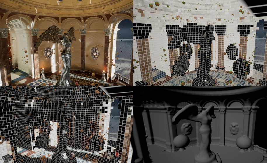
Probes may be stuck inside geometry (even after relocation attempts to move them), exist in spaces without nearby geometry, or be far enough outside the play space that they are never relevant. In these cases, there is no need to spend time tracing and shading rays or updating the irradiance and distance texture atlases for these probes.
We considered a lot of situations, and we add two more probe state to state classification.
Classify just likes a state machine, it controls each probe should be updated, sampled or not. There are four states of probe in our method:
#define DDGI_PROBE_STATE_INACTIVE 0
#define DDGI_PROBE_STATE_ACTIVATED 1
#define DDGI_PROBE_STATE_ACTIVE 2
#define DDGI_PROBE_STATE_SLEEP 3-
DDGI_PROBE_STATE_INACTIVE: Not a valid probe to be sampled, not to update it either.
- Probe is too far from geometry.
- Probe was stuck inside geometry (even after relocation attempts to move them).
-
DDGI_PROBE_STATE_ACTIVATED: When updated this probe, we will mark it as activated.
- It means we recently activated it and it's very important recently. So we will try update it (even it is in camera backface).
-
DDGI_PROBE_STATE_ACTIVE
- In order for overhead to be spread evenly, probe budget was set in one frame. We use rotation request to update a part of probes each frame.Those probes that in request part will be marked as active.
-
DDGI_PROBE_STATE_SLEEP: Not update(tracing ray) this probe, but sample it.
- In camera backface.
- In order for overhead to be spread evenly, probe budget was set in one frame. We use rotation request to update a part of probes each frame.Those probes that not in request part will be marked as sleep.
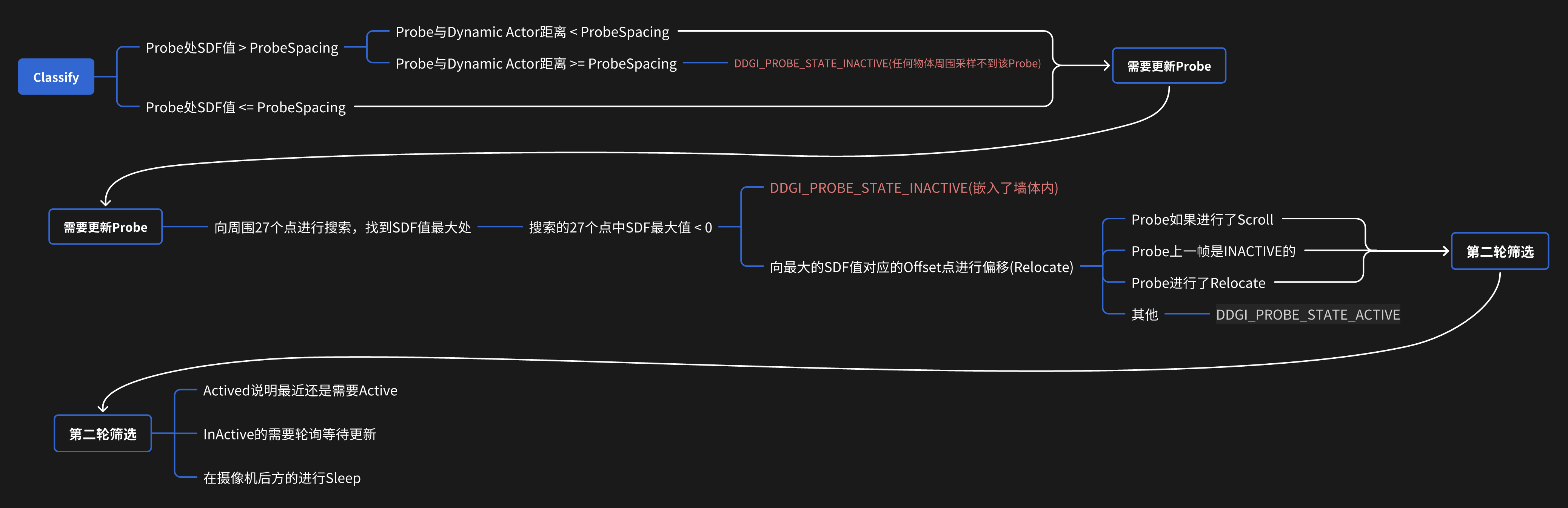
In the early days, I only added DDGI_PROBE_STATE_SLEEP for spread overhead evenly and stop update probes that in camera backface. But those probes which was activated still need to be active to get better and faster scene change response.So DDGI_PROBE_STATE_ACTIVATED was also added to probe state machine.
For cascade probes, we have cascade budget:
- We update each cascade probe by
uint64 cascadeFrequencies[] = { 2, 3, 5, 7 };, which means theith cascade probe will update everycascadeFrequencies[i]frame. - Our method only updates one cascade per frame. This means that when the frame count can be divided by two or more
cascadeFrequencies, we will only update the smallest cascade. - You can open
r.rtgi.AlwaysUpdate 1,which will update all cascade every frame.
For probes in a specific cascade, we have probe budget:
- We use rotation request to update a part of probes each frame.
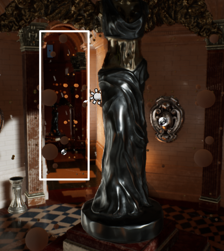
We shift probe origin towards to the view direction for better view frustum coverage when place probes. This feature can be opened by r.rtgi.RelocateProbeVolumeOriginWhenViewDirectionChanged.
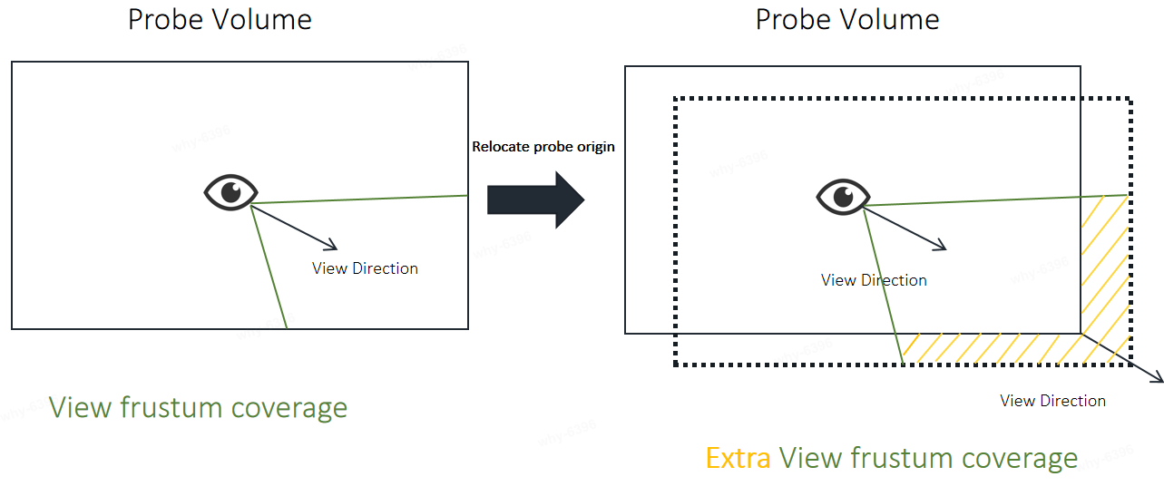
There are more probes in frustum after r.rtgi.RelocateProbeVolumeOriginWhenViewDirectionChanged feature opened.
| Close | Open |
|---|---|
 |
 |
For more details, please read
float3 SampleDDGIIrradiance()function
We use Chebyshev's inequality to calculate the probability of visibility between a Probe and the shading point, leveraging the VSSM concept.
This requires the additional recording of certain information, including:
-
$E(w):$ The irradiance received by the probe from the hemisphere in the direction of$𝑤$ . -
$r(w):$ The distance from the probe to the closest object visible in the direction of$𝑤$ . (Average stored on the hemisphere) -
$r^2(w):$ The square of the distance from the probe to the closest object visible in the direction of$w$ . (Average stored on the hemisphere)
Chebyshev's inequality:
Where
Finally, the calculated probability will be raised to the power of 3. This is a subjective parameter, equivalent to aiming for a lower probability of light leakage.
// Visibility weight (Chebyshev)
if (biasedPosToProbeDist > probeDistanceMean)
{
    float probeDistanceVariance = abs(probeDistanceMean * probeDistanceMean - probeDistanceMean2);
    float chebyshevWeight = probeDistanceVariance / (probeDistanceVariance + Square(biasedPosToProbeDist - probeDistanceMean));
    weight *= max(chebyshevWeight * chebyshevWeight * chebyshevWeight, 0.05f);
}
This solves the issue of Visibility.
However, there may still be some light leakage caused by self-shadow bias, so we need to add a bias on the shading surface.
-
$n$ — Normal of shading point -
$\omega_0$ — Direction from the shading point to the camera -
$D$ — The minimum axial distance between probes -
$B$ — A user-tunable floating point scalar, 0.3f worked well for most scenes.
| Without Bias | With Bias |
|---|---|
 |
 |
Although we have Chebyshev testing to exclude probes that may cause light leakage or shadow leakage, Chebyshev testing is not as effective when a probe is very close to a wall.
-
For probes close to a wall:At extreme angles, the collection of lighting information may not be comprehensive. For example, in the diagram below, some light sources may not be captured by the probe due to wall protrusions.
-
For probes located inside a wall:They will not be sampled during shading, resulting in a reduced amount of information available for the shading point. Therefore, it is necessary to move the probes outside the surface.
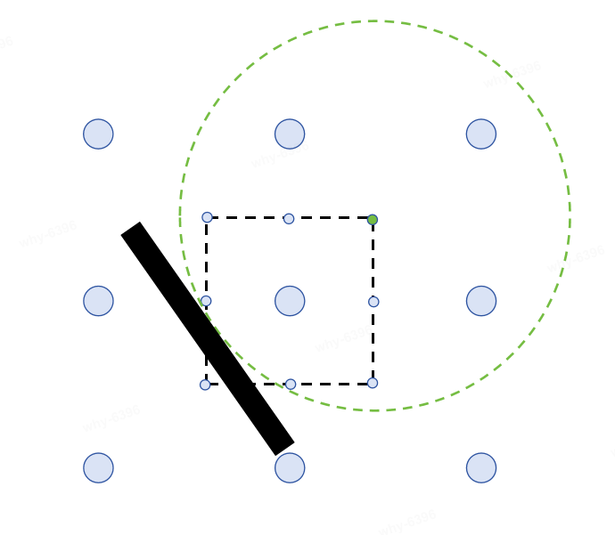
Therefore, we need to try to avoid probes being very close to the wall surface by offsetting their positions to ensure they are outside the surface. In summary, our requirements are as follows:
- For probes located inside the surface of an object, we aim to move them to the surface outside.
- For probes located outside the object's surface but close to it, we aim to move them as far away from the surface as possible.
- To maintain the relative positions of the 8 probes, we need to set a constraint on the probe offset, ensuring it does not exceed half the distance between probes.
Our approach is to try offsetting the probe half the distance between probes around 27 points and calculate the SDF value after the offset. We choose the offset with the highest SDF value among these options, aiming to maintain the probe as close to the wall surface as possible without affecting the relative positions of surrounding probes.
In the diagram below, the black area represents the wall, and the black dashed box represents the constraint of not exceeding half the distance between probes. The green point indicates the location with the highest SDF value, so the probe will be relocated to the green point.
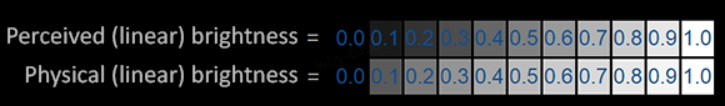
While shading at the shading point, we need to perform trilinear interpolation on the surrounding eight probes. As our calculations have been done in linear space, however, human perception of lighting is in a nonlinear space (That's why gamma correction exists). Interpolation should also be done in the nonlinear space.
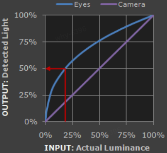
As shown in the figure:
If there is a point want to interpolate between the point A with 0.0 brightness and the point B with 0.5 brightness. It is better to do in perceived linear brightness(Encode in gamma).It has more details in dark areas and more suitable for human eye perception.
When shading, we will apply gamma correct to the irradiance before interpolation, and then revert back to linear space after interpolation to match the rendering pipeline( The rendering pipeline will always apply tone mapping in the end).
To reuse data from previous frames, interpolation is performed between the data updated each time and the data from the previous update. This not only reduces screen jitter but also decreases the sampling quantity. We provide the parameter ProbeHistroyWeight for adjusting the weight of historical frames:
However, sometimes rapid changes in lighting require a quick response from the visuals. Therefore, we also offer a ProbeChangeThreshold parameter; if the change exceeds this threshold, it is deemed unnecessary to reuse historical frames or may require an appropriate reduction in historical frame weight.
Lastly, interpolation is conducted using historical frames:
If the irradiance probes are slow to converge, abrupt lighting changes in a scene can create noticeable lag in the diffuse indirect illumination.
Encoding:
result.rgb = pow(result.rgb, ProbeInvertIrradianceEncodingGamma);Decoding:
float3 exponent = ProbeIrradianceEncodingGamma * 0.5f;
probeIrradiance = pow(probeIrradiance, exponent);
When interpolating:
In the speech GTC China: RTXGI 在游戏剑侠情缘网络版三家园系统中的应用 .The author mentioned that the scene appears dark in indirect lighting due to the albedo being too dark. To address this issue, they have provided a parameter to adjust the albedo. Here, we also provide a scaling parameter IndirectLightingIntensity to adjust the indirect lighting.
| IndirectLightingIntensity = 1(Default) | IndirectLightingIntensity = 2.2 |
|---|---|
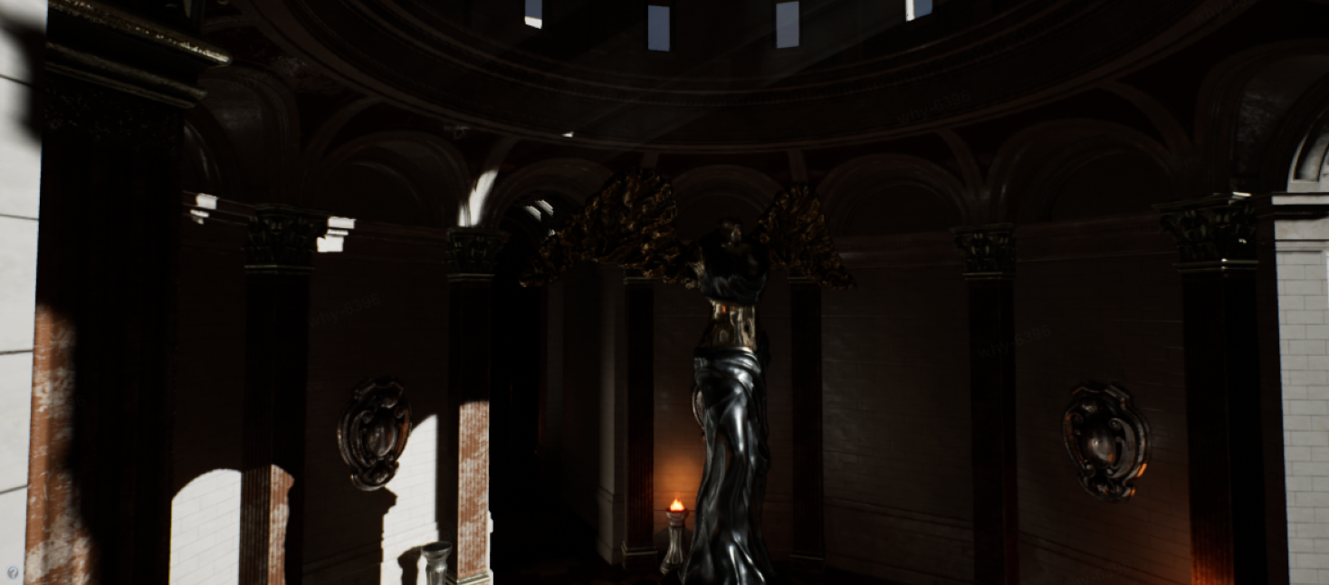 |
 |
Here are some math tips for you to understand the code better.
When the probe ray traces to the surface of an object, we can obtain its radiance. Therefore, uniform sampling on the probe is a very important issue. Let's simplify our problem: how evenly distribute n points on a sphere?
The Fibonacci sphere algorithm(https://arxiv.org/pdf/0912.4540.pdf) is what we need.
DDGI related:
- Zander Majercik, Jean-Philippe Guertin, Derek Nowrouzezahrai, and Morgan McGuire, Dynamic Diffuse Global Illumination with Ray-Traced Irradiance Fields, Journal of Computer Graphics Techniques (JCGT), vol. 8, no. 2, 1-30, 2019 Available online http://jcgt.org/published/0008/02/01/
- Zander Majercik, Adam Marrs, Josef Spjut, and Morgan McGuire, Scaling Probe-Based Real-Time Dynamic Global Illumination for Production, Journal of Computer Graphics Techniques (JCGT), vol. 10, no. 2, 1-29, 2021 Available online http://jcgt.org/published/0010/02/01/
- Blog "Dynamic Diffuse Global Illumination" written by Morgan McGuire.
- RTX Global Illumination (RTXGI) from NVIDIAGameWorks
- GDC2019: Ray-Traced Irradiance Fields (Presented by NVIDIA)
- GDC2019: Scalable Real-Time Global Illumination for Large Scenes
- GTC China: RTXGI 在游戏剑侠情缘网络版三家园系统中的应用 https://www.nvidia.cn/on-demand/session/gtccn2020-cns20991/
Voxelization related:
- The Basics of GPU Voxelization by NVDIA
- Elmar Eisemann and Xavier Décoret. 2008. Single-pass GPU solid voxelization for real-time applications. In Proceedings of Graphics Interface 2008 (GI '08). Canadian Information Processing Society, CAN, 73–80.
Sparse Distance Field:
- SIGGRAPH 2022 Advances in Real-Time Rendering in Games: Lumen: Real-time Global Illumination in Unreal Engine 5
Others:
- The Fibonacci sphere algorithm. https://arxiv.org/pdf/0912.4540.pdf
- Mark Jarzynski and Marc Olano, Hash Functions for GPU Rendering, Journal of Computer Graphics Techniques (JCGT), vol. 9, no. 3, 21-38, 2020 Available online http://jcgt.org/published/0009/03/02/
- Gamma Correct https://learnopengl-cn.github.io/05%20Advanced%20Lighting/02%20Gamma%20Correction/