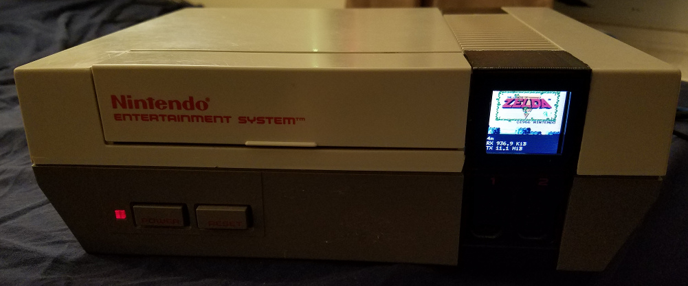
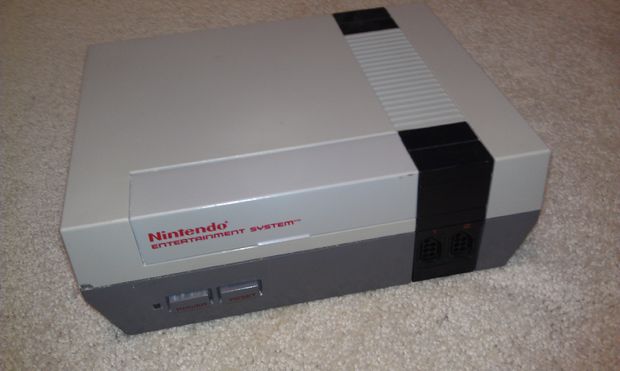
Using an Old Nintendo Entertainment system case, produce a highly functional home router using a RaspberryPI 3
Download "RASPBIAN JESSIE LITE" https://www.raspberrypi.org/downloads/raspbian/
Create your new hard disk for DashboardPI
Insert the microSD to your computer via USB adapter and create the disk image using the
ddcommandLocate your inserted microSD card via the
df -hcommand, unmount it and create the disk image with the disk copyddcommand$
df -h/dev/sdb1 7.4G 32K 7.4G 1% /media/XXX/1234-5678$
umount /dev/sdb1Caution: be sure the command is completely accurate, you can damage other disks with this command
if=location of RASPBIAN JESSIE LITE image file of=location of your microSD card
$
sudo dd bs=4M if=/path/to/raspbian-jessie-lite.img of=/dev/sdb(note: in this case, it's /dev/sdb, /dev/sdb1 was an existing factory partition on the microSD)
Setting up your RaspberriPi
Insert your new microSD card to the raspberrypi and power it on with a monitor connected to the HDMI port
Login
user: pi pass: raspberry
Change your account password for security
sudo passwd pi
Enable RaspberriPi Advanced Options
sudo raspi-config
Choose:
1 Expand File System
9 Advanced Options
A2 Hostnamechange it to "NESRouter"
A4 SSHEnable SSH Server
A7 I2CEnable i2c interface
Enable the English/US Keyboard
sudo nano /etc/default/keyboard
Change the following line:
XKBLAYOUT="us"
Setup the simple directory l command [optional]
vi ~/.bashrcadd the following line:
alias l='ls -lh'
source ~/.bashrc
Fix VIM default syntax highlighting [optional]
sudo vi /etc/vim/vimrcuncomment the following line:
syntax on
Reboot your PI to get the latest changes
reboot
Old Nintendo Case from a broken NES (remove all the old contents inside the case, leaving only the outside frame, the power / reset buttons and the controller connections)
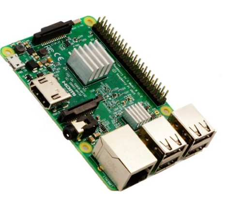
Raspberry Pi 3 Model B
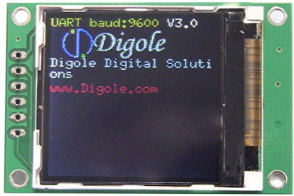
1.44" Serial:UART/I2C/SPI TFT LCD 128x128 Display Module
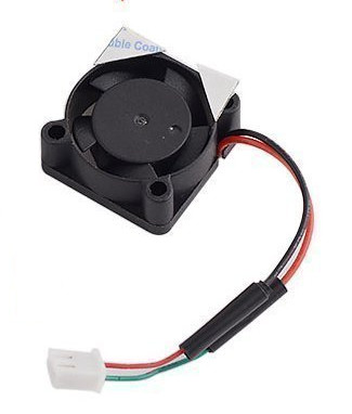
5V 0.1A Mini Fan Raspberry Pi
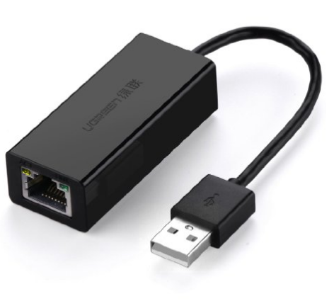
Ugreen USB 2.0 to 10/100 Fast Ethernet Lan Wired Network Adapter
Update local timezone settings
sudo dpkg-reconfigure tzdata
select your timezone using the interface
Please note, before this becomes a router we're plugging in the RaspberryPi to an existing network via its ethernet port to install the following packages
sudo apt-get update && sudo apt-get -y upgrade
sudo apt-get install dnsmasq hostapd vim
sudo apt-get install vim git python-smbus i2c-tools python-imaging python-smbus build-essential python-dev rpi.gpio python3 python3-pip libi2c-dev
sudo vi /etc/dhcpcd.conf
Add the following line:
denyinterfaces wlan0
sudo vi /etc/network/interfaces
Edit the wlan0 section so that it looks like this:
auto lo
iface lo inet loopback

iface eth0 inet manual

auto wlan0
iface wlan0 inet static
    address 10.0.10.1
    netmask 255.255.255.0
    network 10.0.10.0
    broadcast 10.0.10.255

auto eth1
iface eth1 inet static
    address 10.0.20.1
    netmask 255.255.255.0
    network 10.0.20.0
    broadcast 10.0.20.255
Reload DHCP Server and bounce the configuration for eth0 and wlan0 connections
sudo service dhcpcd restart
sudo ifdown eth0; sudo ifup wlan0
sudo vi /etc/hostapd/hostapd.conf
# This is the name of the WiFi interface we configured above
interface=wlan0

# Use the nl80211 driver with the brcmfmac driver
driver=nl80211

# This is the name of the network
ssid=NintendoWiFi

# Use the 2.4GHz band
hw_mode=g

# Use channel 6
channel=6

# Enable 802.11n
ieee80211n=1

# Enable WMM
wmm_enabled=1

# Enable 40MHz channels with 20ns guard interval
ht_capab=[HT40][SHORT-GI-20][DSSS_CCK-40]

# Accept all MAC addresses
macaddr_acl=0

# Use WPA authentication
auth_algs=1

# Require clients to know the network name
ignore_broadcast_ssid=0

# Use WPA2
wpa=2

# Use a pre-shared key
wpa_key_mgmt=WPA-PSK

# The network passphrase
wpa_passphrase=password

# Use AES, instead of TKIP
rsn_pairwise=CCMP
We can check if it's working at this stage by running (but doesn't have full internet connectivity yet):
sudo /usr/sbin/hostapd /etc/hostapd/hostapd.conf
sudo vi /etc/default/hostapd
Find the line
#DAEMON_CONF=""
and replace it with
DAEMON_CONF="/etc/hostapd/hostapd.conf"
Configure DNSMASQ
sudo mv /etc/dnsmasq.conf /etc/dnsmasq.conf.orig
sudo vi /etc/dnsmasq.conf
bind-interfaces           # Bind to the interface to make sure we aren't sending things elsewhere
server=8.8.8.8            # Forward DNS requests to Google DNS
domain-needed             # Don't forward short names
bogus-priv                # Never forward addresses in the non-routed address spaces.

# Assign IP addresses w/infinite lease time (for device usage stats)
dhcp-range=wlan0,10.0.10.100,10.0.10.200,255.255.255.0,10.0.10.255,infinite
dhcp-range=eth1,10.0.20.100,10.0.20.200,255.255.255.0,10.0.20.255,infinite
SET UP IPV4 FORWARDING
sudo vi /etc/sysctl.conf
[uncomment] net.ipv4.ip_forward=1
Activate it immediately with
sudo sh -c "echo 1 > /proc/sys/net/ipv4/ip_forward"
sudo iptables -t nat -A POSTROUTING -o eth0 -j MASQUERADE
sudo iptables -A FORWARD -i eth0 -o eth1 -m state --state RELATED,ESTABLISHED -j ACCEPT
sudo iptables -A FORWARD -i eth1 -o eth0 -j ACCEPT
sudo iptables -A FORWARD -i eth0 -o wlan0 -m state --state RELATED,ESTABLISHED -j ACCEPT
sudo iptables -A FORWARD -i wlan0 -o eth0 -j ACCEPT
Save iptables settings for next reboot
sudo sh -c "iptables-save > /etc/iptables.ipv4.nat"
Create ipv4 rules file (with new contents)
sudo vi /lib/dhcpcd/dhcpcd-hooks/70-ipv4-nat
iptables-restore < /etc/iptables.ipv4.nat
Restart Services
sudo service hostapd start
sudo service dnsmasq start
sudo reboot
If you would like hosts on your network to have static ips please use the following
Aquire the hosts currently connected via DHCP
vi /var/lib/misc/dnsmasq.leases
Add the MAC Address (from output above) and the IP address you would like to assign them to
sudo vi /etc/dnsmasq.conf
# main desktop
dhcp-host=12:34:56:78:9a:bc,10.0.20.20
Note: This will assign the network interface with the MAC Address: 12:34:56:78:9a:bc to IP address 10.0.20.20. The IP address listed does NOT have to be in the DHCP range given, just on the same subnet. My main desktop above is on subnet eth1:10.0.20.0, so I gave it IP Address of 10.0.20.20.
sudo apt-get install ufw
Allow port 22 for public use (for remote network access)
sudo ufw allow 22
Allow all ports on my local network
sudo ufw allow from 10.0.10.0/24
sudo ufw allow from 10.0.20.0/24
Allow web ports to everyone
sudo ufw allow 80
Allow secure web ports to everyone
sudo ufw allow 443
Enable UFW and check the status
sudo ufw --force enable
sudo ufw status
Fix BUG with UFW not starting on startup
sudo su
crontab -e
Add the following line:
@reboot /bin/sleep 60; ufw --force enable
-
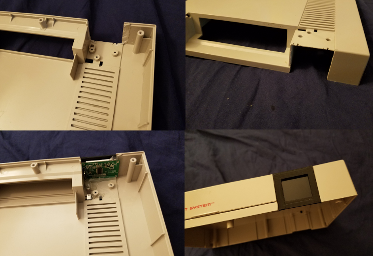
Using a 3D printer print the Digole Display frame "NESPanel" in the
/construction/display-frame/folder. [if you don't have a 3D printer you could delicately cut a square hole for the Digole Display with a Dremel tool] -
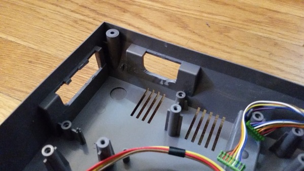
Cut the following holes open in the back and side of the case to allow for the small fan to be fastened on the side and the power/ethernet and USB ethernet cables to get in through the back.
- Unscrew the top right black panel from the NES and cleanly cut a large enough square hole to mount your digole display. Hot Glue the display in place with the "NESPanel" 3D printed frame over the top of it.
- Mount the RaspberryPi in the middle of the bottom of the empty NES case, fasten by glue or a small screw through the bottom. Using a 270 ohm resister, connect the "power on LED" of the NES to the 5V and GND pins in the Raspberry Pi (short LED lead is the ground). Connect the small fan to the 5V and GND pins as well to have it run when the unit starts up, glue the fan against the hole in the side for it.
Connect the following pins to the pins on the RaspberryPi
VCC is connected to 3v
GND is ground
DATA is SDA
CLOCK is SCL
Now you should see the device in your i2cdetect command
i2cdetect -y 1
it should show up in the grid of text as 27
sudo apt-get install ifstat memcached python-memcache postgresql postgresql-contrib python-psycopg2
sudo vi /etc/postgresql/9.4/main/pg_hba.conf
Add the following line to the end of the file: local all pi password
sudo -i -u postgres
psql
create role pi password 'password here';
alter role pi login;
alter role pi superuser;
\du
(you should see your PI user with the permissions granted)
create database network_stats;
\q
exit
psql -d network_stats
Run the following queries:
CREATE TABLE traffic_per_minute ( id serial, time timestamp without time zone NOT NULL, eth0_down real, eth0_up real, eth1_down real, eth1_up real, wan0_down real, wan0_up real );
CREATE UNIQUE INDEX time_idx ON traffic_per_minute (time);
Copy the "logging" folder of code from this project to the home directory of your RPi
crontab -e
Add this line
@reboot /bin/sleep 60; nohup python /home/pi/logging/networkUsage.py >/dev/null 2>&1
crontab -e
add the following line
*/5 * * * * python /home/pi/logging/trafficSummary.py
Copy the "display" folder of code from this project to the home directory of your RPi
Run it as follows
$
python /home/pi/display/NESRouter.py
Setup the display script to run at startup
crontab -e
Add this line
@reboot nohup python /home/pi/display/NESRouter.py >/dev/null 2>&1
Verify the display starts working on reboot
sudo reboot
Install the local usage/statistics website [http://10.0.10.1]
sudo apt-get update && sudo apt-get upgrade -y
sudo apt-get install apache2
sudo service apache2 restart
Remove default pages
cd /var/www
sudo rm -rf html
Copy 'webportal' folder from this project to your home folder on your RPi and create the symlink for apache to use
cd /var/www
sudo ln -s /home/pi/webportal html
cd /var/www/html
chmod +x *.py
sudo a2enmod cgi
sudo vi /etc/apache2/sites-enabled/000-default.conf
Enable Python CGI Scripting
Add inside the <virtual> tag
<Directory /var/www/html> Options +ExecCGI AddHandler cgi-script .py </Directory>
sudo service apache2 restart
You can now visit the local HTTP site [http://10.0.10.1]
sudo apt-get update
sudo apt-get install ipfm
sudo mv /etc/ipfm.conf /etc/ipfm.conf-bak
sudo vi /etc/ipfm.conf
Create with the following contents:
# Global variables
# IPFM can monitor only one device. DEVICE eth0
# GLOBAL LOGGING CONFIGURATION LOG
FILENAME "/var/log/ipfm/%Y_%d_%m/%H_%M"
# log every minute DUMP EVERY 1 minute
# clear statistics each day CLEAR EVERY 24 hour SORT IN RESOLVE
sudo service ipfm start
Upload your own 128x128 file to the following URL:
http://www.digole.com/tools/PicturetoC_Hex_converter.php
Choose your image file to upload, add what size you want it to be on the screen (Width/Height)
Select "256 Color for Color OLED/LCD(1 byte/pixel)" in the "Used for" dropdown
Obtain the hex output.
Add the hex output to a display/build/ header (.h) file, use the other ones as guides for syntax.
Include the new file in the digole.c file
#include "myimage.h
Include a new command line hook to your image file in the. Note: the command below is saying draw your image at position 10 pixels over 10 pixels down. You can change it to different X,Y coordinates, you can also change the values 128,128 to whatever size your new image actually is.
} else if (strcmp(digoleCommand, "myimage") == 0) {
drawBitmap256(10, 10, 128, 128, &myimageVariableHere,0); // myimageVariableHere is defined in your (.h) file
}
Now rebuild (ignore the errors) below to have your new image render with the following command.
$
./digole myimage
Re-Building [Included] Digole Display Driver for your optional changes
$
cd display/build
$
gcc digole.c
$
mv a.out ../../digole
$
chmod +x ../../digole
